Renogy Solar
Renogy Solar
I finished installing the new renogy dual panel solar system. I tried uploading a video but i dont know if it worked. If someone sees this let me know if the video works on your end and i will post more.
Re: Renogy Solar
I couldn't play the Quicktime. The MP4 downloaded 99.9% of the way (7.5MB of 7.5MB) but then wouldn't quite download all the way so I couldn't play it (just kept getting "this hasn't finished downloading" message). So, no viewing for me. Boo!
1999 Concourse
Re: Renogy Solar
hmmm, guess i should just forget videos on here and stick with pictures instead? I spoke with renogy tech, they said i cant hook one cable to the positive on one battery and then hook negative to the negative terminal on the opposite battery or i would be kicking it up to 24 volts?
Re: Renogy Solar
Well maybe it's just me on the video. But you could PM "Manitou" and ask him - it's his forum.
For example, I have three 12-volt batteries in my house bank. So a positive wire (jumper) starts at battery A, then goes to the positive terminal on battery B, then another jumper goes from the positive terminal of battery B to the positive terminal on battery C. From the positive terminal on battery C my positive comes off to a bus bar (and to the rest of the system).
On the negative, it's the reverse. A negative jumper wire starts at battery C, and goes to the terminal on battery B, then another jumper from B to A. Then a wire comes from battery A off to a bus bar to power my system.
Two reasons for the way mine are hooked up:
1) I have a 12-volt system and 12 volt batteries, so they are in parallel.
2) It's best to have the power coming off to be as "balanced" as possible as it draws through the battery bank. There are a number of ways to do this, but the worst thing is to have both of your wires (leading to loads/charging) coming off one battery. That then draws the most power (always) from the first battery, less from the second, and less from the third (etc.). Much better is to have the "off coming leads" coming from opposite end (like how I describe above). There are other schemes to improve things even more, but the above mentioned way is the "big bank for the buck" simple improvement. The other ways make much smaller additional improvements.
So in my scheme, the positive from the solar controller would go to one battery (C) and the negative from the solar controller would go to another battery (A). In reality they don't go straight to the batteries but rather to switches or bus bars or power posts. But it's the same electrically.
So... how are your batteries set up (voltage, jumpers, etc.? (not the solar but just the battery bank itself)
To double-check on what Renogy is telling you, could you describe your battery bank and how you (independently of the solar) have them connected to each other? That's what determines your battery bank voltage (how they are set up as a bank -- independently of the solar controller).dougm wrote: I spoke with renogy tech, they said i cant hook one cable to the positive on one battery and then hook negative to the negative terminal on the opposite battery or i would be kicking it up to 24 volts?
For example, I have three 12-volt batteries in my house bank. So a positive wire (jumper) starts at battery A, then goes to the positive terminal on battery B, then another jumper goes from the positive terminal of battery B to the positive terminal on battery C. From the positive terminal on battery C my positive comes off to a bus bar (and to the rest of the system).
On the negative, it's the reverse. A negative jumper wire starts at battery C, and goes to the terminal on battery B, then another jumper from B to A. Then a wire comes from battery A off to a bus bar to power my system.
Two reasons for the way mine are hooked up:
1) I have a 12-volt system and 12 volt batteries, so they are in parallel.
2) It's best to have the power coming off to be as "balanced" as possible as it draws through the battery bank. There are a number of ways to do this, but the worst thing is to have both of your wires (leading to loads/charging) coming off one battery. That then draws the most power (always) from the first battery, less from the second, and less from the third (etc.). Much better is to have the "off coming leads" coming from opposite end (like how I describe above). There are other schemes to improve things even more, but the above mentioned way is the "big bank for the buck" simple improvement. The other ways make much smaller additional improvements.
So in my scheme, the positive from the solar controller would go to one battery (C) and the negative from the solar controller would go to another battery (A). In reality they don't go straight to the batteries but rather to switches or bus bars or power posts. But it's the same electrically.
So... how are your batteries set up (voltage, jumpers, etc.? (not the solar but just the battery bank itself)
1999 Concourse
Re: Renogy Solar
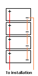
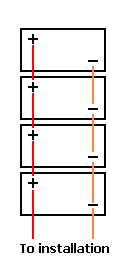
Below is a link to a page that discusses the various methods of connecting batteries in parallel to make a bank (series is different as the voltages are additive). The method I was describing is the "Method 2" they show and is how I have my three 12-volt batteries connected into a bank. Like so:

So as you can see above, anything I connect to the bus bars coming off my battery will by definition have the positive and negative connected to opposite ends of the bank. But the bank itself is a 12-volt bank, wired in parallel. (Again, series is different, and adds the voltage of all the batteries.)
"Method 1" is the not-so-good way to connect more than two batteries in parallel (causes imbalance):

http://www.smartgauge.co.uk/batt_con.html

So as you can see above, anything I connect to the bus bars coming off my battery will by definition have the positive and negative connected to opposite ends of the bank. But the bank itself is a 12-volt bank, wired in parallel. (Again, series is different, and adds the voltage of all the batteries.)
"Method 1" is the not-so-good way to connect more than two batteries in parallel (causes imbalance):

http://www.smartgauge.co.uk/batt_con.html
1999 Concourse
Re: Renogy Solar
Mine are hooked up like the last image, i have 2 batteries right now. Positive to positive and negative to negative with the solar cables poitive and negative hooked to the same battery. Once i got everything installed and put back together i plugged in the remote monitor and checked it at noon when the sun was directly overhead and it was only putting out about 4 to 5 amps, the voltage on the other hand was like 36 volts from the panels. Amperage just seems a bit low to me considering how they bragged this system up as being better than a standard monocrystaline panel. That 4 to 5 amps was short lived though and after a short time it was down to like 2 to 3 amps most of the day, then as the sun went down it slowly went to 0 amps. I took my time, it took me two days to do the install so i know i have everything installed properly as per Renogy. Maybe i better just assume im going to need two more panels?
Re: Renogy Solar
Okay, so a couple of things.
One is that I would change the jumper arrangement on your batteries to match the Method 2. Reason is otherwise the battery that both the cables are coming off of is doing most of the work, and the other one is coasting more. So you want the "final" negative cable and the "final" positive cable (the ones leading to your loads and charging) coming off opposite batteries.
Okay, on your solar, if you are seeing something like 36 volts and 5 amps (coming from the panels), that means your panels are hooked up in series. In series, the volts add up, and the amps stay the same (in parallel, the volts stay the same and the amps add up).
There is nothing wrong with having the panels in series - I have mine set up this way on purpose. So, ~36 volts goes into the charge controller (must be MPPT to do this) at around 5 amps. This is nice because I can have a 25' 8AWG wire leading out to the panels (I use them as ground panels) and still have very little voltage drop. Easy to put me in the shade and the panels in the sun that way. If I had the panels in parallel I'd have 10 amps coming in vs. 5 on that wire, and either too much voltage drop or change to a huge thick wire.
When my (approximately) 36 volts and 5 amps get to the solar controller, the MPPT controller works its magic, and what comes out the other side (leading to the batteries) is 13-15 volts (depending on charging stage and battery temp) and around 10 amps. Magic!
So, if you are seeing 36 volts on the panel side, you definitely have them wired in series. If you want that, great. If not, you should change the panel wiring to a parallel setup. Then you will see like 18 volts coming in from the panels (at twice the amps).
If you are seeing 36 volts on the battery side (coming OUT of the controller and going to the batteries), then perhaps your controller thinks you have a 24 volt battery system. This could be for a number of reasons.
1) It was "told" in the settings that that's what you have.
2) It auto-detected a 24-volt battery setup (which would seem to mean your batteries might be connected in series).
3) It's broken.
If you DO have your batteries in parallel (12 volts) and the controller is actually putting out 36 volts (my guess is it's not and something else is afoot), you may have ruined your batteries. That would be serious overcharging. But I bet it is something else,like maybe you were reading the display of what the panels were doing, not the solar controller (my display will show me either one, depending on which buttons I press). I'm happy to sleuth with you if you like.
Okay, back you you
BG
PS: Not that more solar is a undesirable, but you should be able to run the basics easily with 200 watts. Now, the panels won't put in more than the batteries can accept (plus your loads you are running at the time), but on days my batteries were "down" I've taken in 60 amp hours in a day. Not too shabby. I don't usually take in more than around 15-25, but that's simply because I don't use anymore than that most days so there is no place for it to "go" (power will only come in if it has a purpose - either filling up the batteries or running a load in real time, for our rigs). But anyway, 200 watts with little voltage drop and a good controller can give a lot of power (for modest demands of course).
1999 Concourse
Re: Renogy Solar
The display shows everything, it showed 36 volts on the panel side going to the controller and it showed 13.6 volts at the battery side.
Re: Renogy Solar
Okay, makes sense. Then the only thing I see "wrong" is that the numbers indicate that you have your panels wired in series. This isn't actually wrong, unless you wanted to have them in parallel. Parallel has been the conventional wisdom for RV installations, but I like series (or series/parallel if more than two panels) and so that's how I have mine. Either way works in the end.
If your panels are wired in parallel, they won't show ~36 volts/5 amps at the panels, but rather ~18 volts/10 amps (when cranking in full sun). In series voltage adds up, amps stay the same; in parallel amperage adds up and volts stay the same. IIRC those panels have a VMP of around 18 volts (or so). (I have similar panels on a boat.)
So... any chance your panels are wired in series? That's what it sounds like from here.
1999 Concourse
Re: Renogy Solar
Yes they are in series because that is how the kit came. It doesnt come with proper plugs to hook them up any other way. Each panel has one male and one female connecter, one being positive and one being negative. The positive on one panel goes to the controler then the negative hooks to the positive on the other panel and last the negative on that panel goes to the controler ground terminal.
